Gear
The gear is a simple machine that can be used to efficiently transfer force and motion.
Connect
(5-10 Minutes)
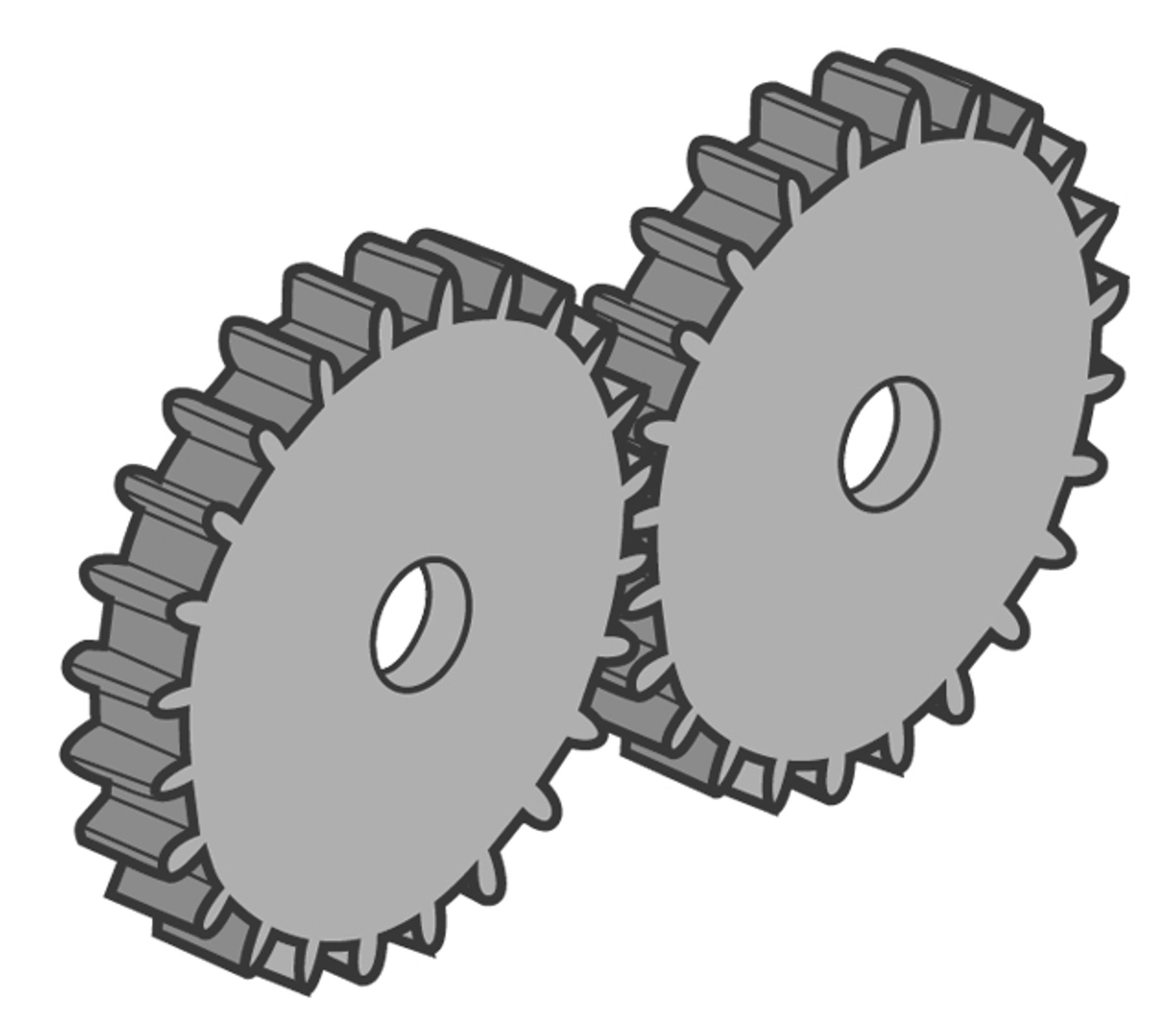
Gears are wheels with teeth that mesh with each other. Because the teeth lock together, they can efficiently transfer force and motion.
Did you know?
Not all gears are round. Some gears are square, triangular, and even elliptical.
The drive gear is the gear that is turned by an outside effort, for instance your hand or an engine. Any gear that is turned by another gear is called a driven gear or follower. The drive gear provides the input force and the driven gear delivers the output force.
Using a gear system can create change in speed, direction, and force. But there are always advantages and disadvantages. For example, you cannot have both more output force and an increase in speed at the same time.
To determine the ratio of which two meshed gears will move relative to each other, divide the number of teeth on the driven gear by the number of teeth on the drive gear. This is called the gear ratio. If a driven gear with 24 teeth is meshed with a drive gear with 48 teeth, there is a 1:2 gear ratio. That means the driven gear will turn twice as fast as the drive gear.
Gears are found in many machines where there is the need to control the speed of rotary movement and turning force. Common examples include power tools, cars, and egg beaters!
Construct
(5-10 Minutes)
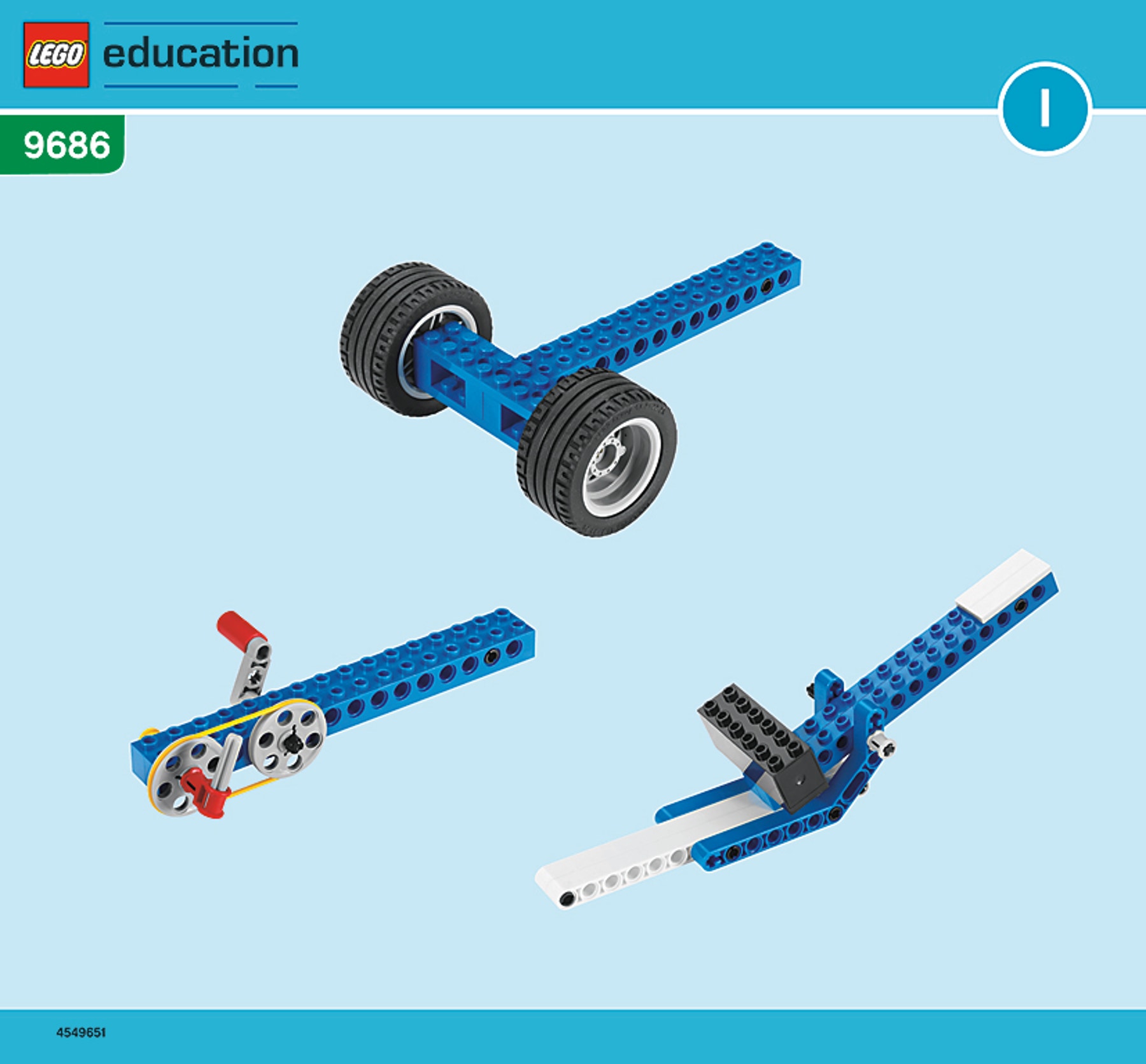
Build the following models. Use the Contemplate ideas below and on the Student Worksheet to learn about each model, one at a time.
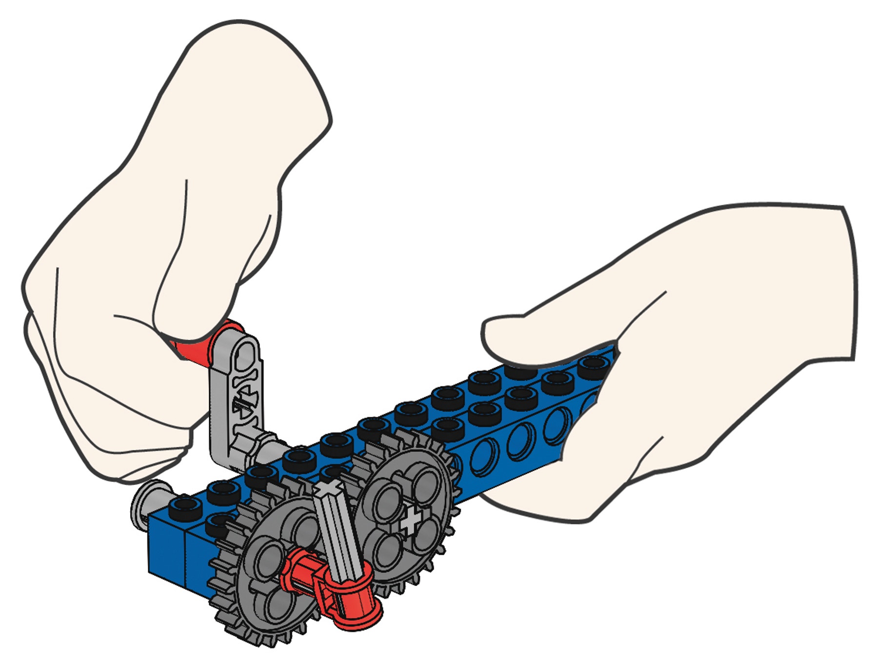
Build G1 book III, page 2
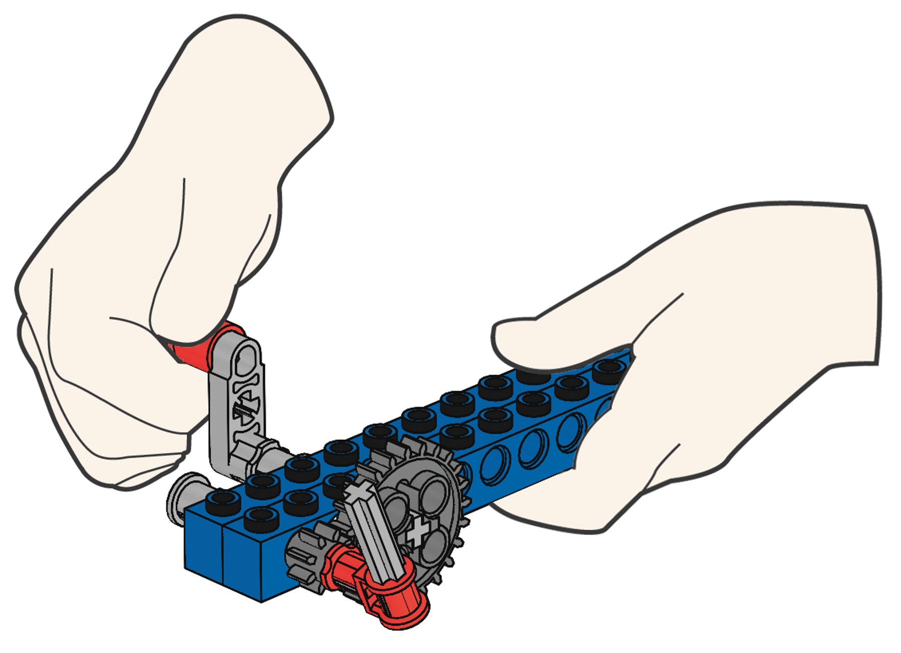
Build G2 book III, page 3
Build G3 book III, page 4
Build G4 book III, page 5 to 6
Build G5 book III, page 7 to 8
Build G6 book III, page 9 to 10
Build G7 book III, page 11 to 14
Build G8 book III, page 15 to 18
Build G9 book III, page 19 to 22
Build G10 book III, page 23 to 25
Contemplate
(10-15 minutes)
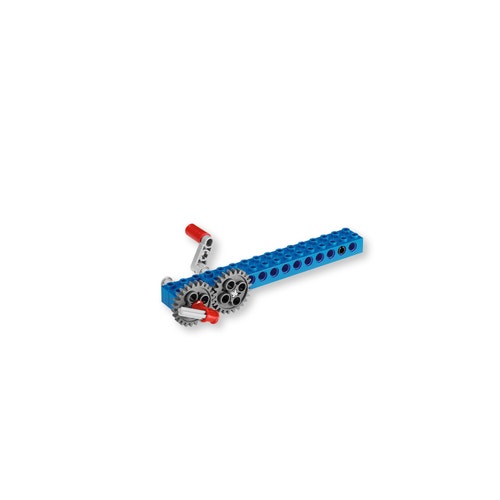
G1
This model shows a 1:1 gear ratio. The speeds of the drive gear and the driven gears are the same, because they have the same number of teeth. The drive and driven gears turn in opposite directions.
G2
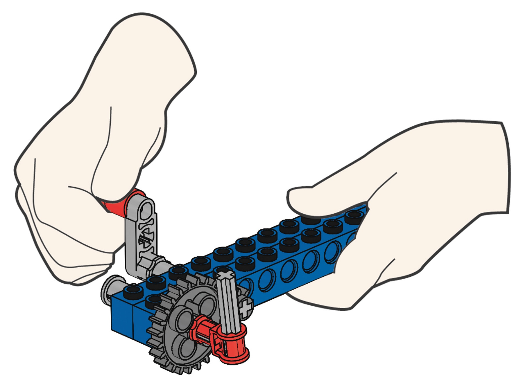
This model shows gearing up. The larger drive gear turns the smaller driven gear, resulting in increased speed, but reduced output force.
G3
This model shows gearing down. The smaller drive turns the larger driven gear, resulting in reduced speed, but increased output force.
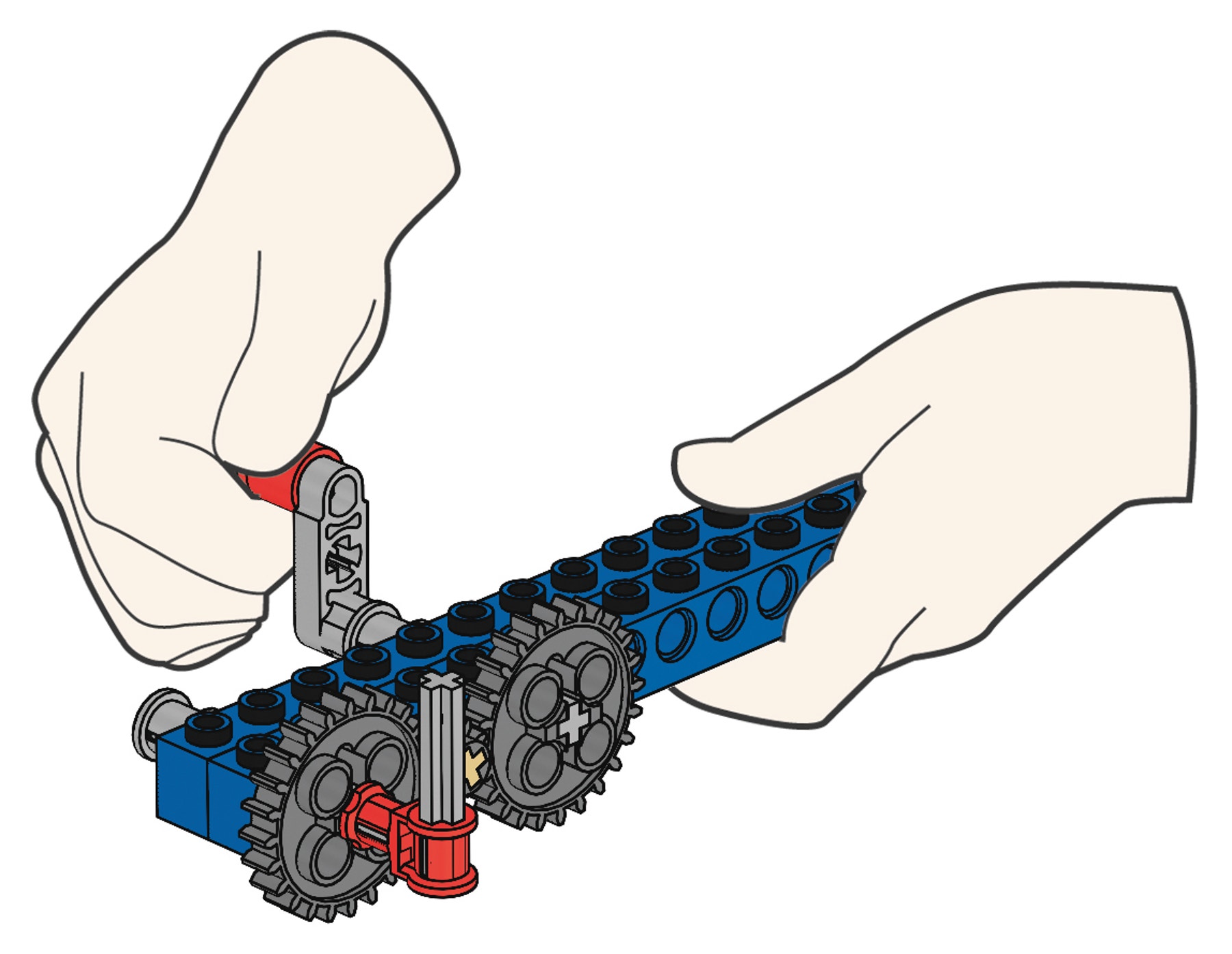
G4
This model shows an idler gearing. The small gear is an idler gear. The idler gear does not affect the speed or output force of either the drive or the driven gears. The drive and the driven gears turn in the same direction and at the same speed.
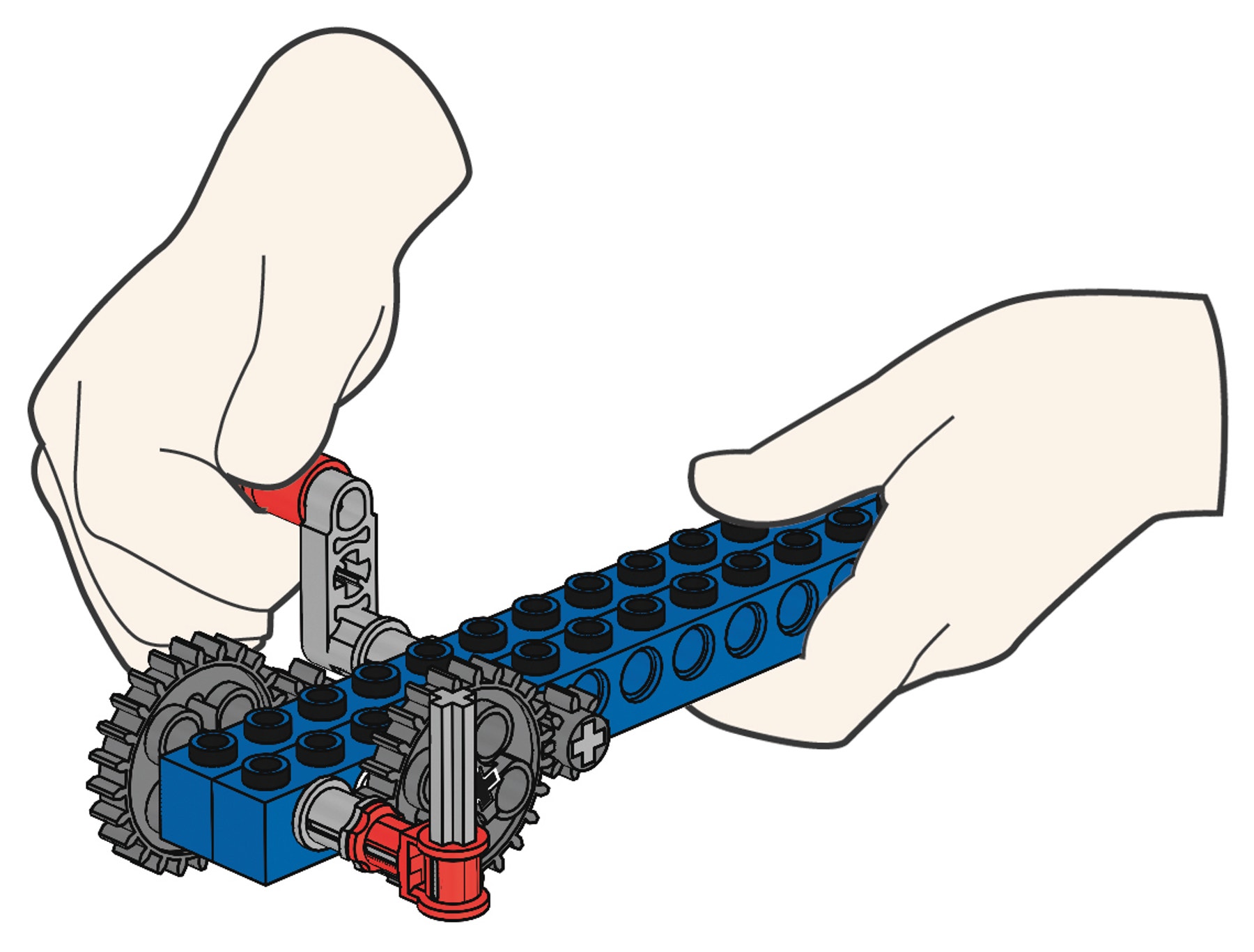
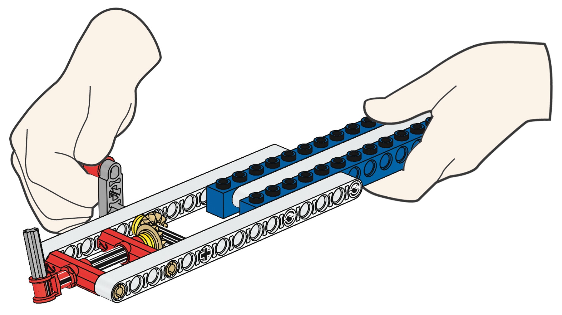
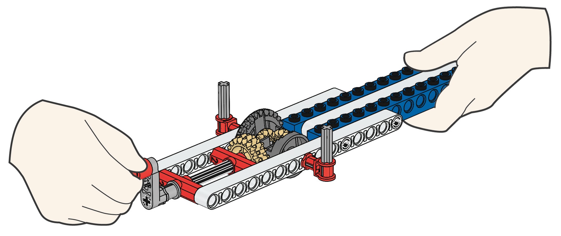
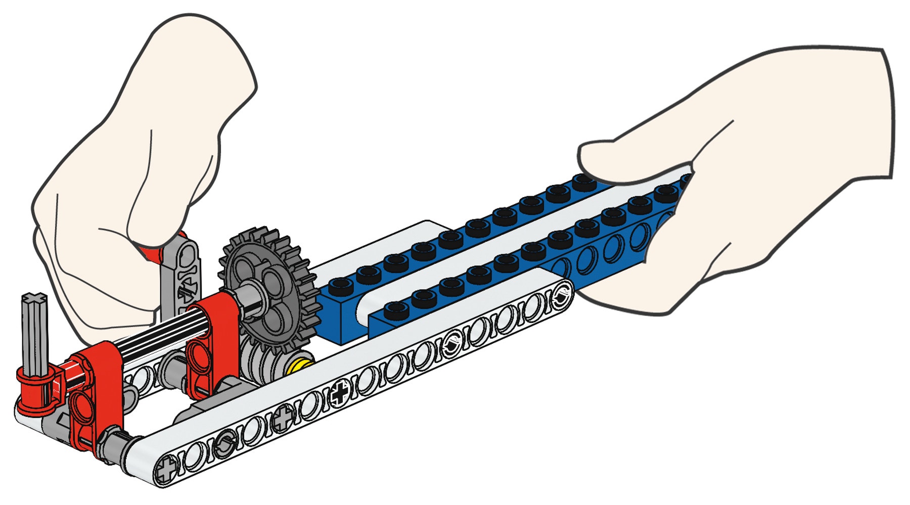
G5
This model shows an example of compound gearing. Because of the way this compound gearing is arranged, the turning speed is significantly reduced and the output force greatly increased. The smaller drive gear slowly turns the larger driven gear. The smaller gear on the same axle as the driven gear is now set in motion and slowly turns the second large driven gear, making it turn even more slowly.
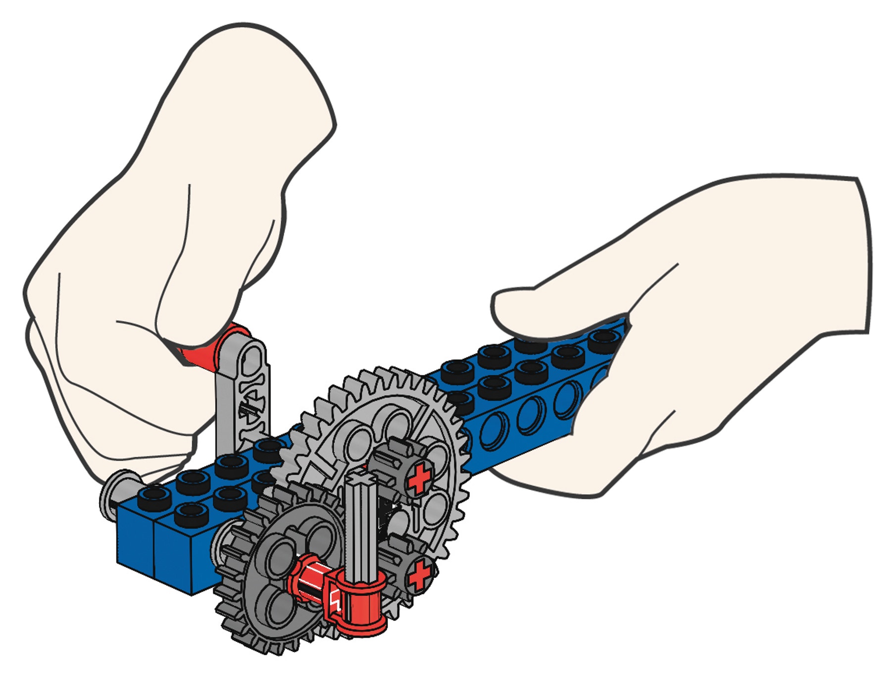
G6
This model shows gears set up for periodic movement: the driven gear turns for a short while and then stops for a moment. Speed is significantly reduced as movement only occurs when the driven gear is meshed with one of the two drive gears.
G7
This model shows an angle gearing. The two meshed bevel gears transfer the speed and force unchanged, but at an angle of 90º.
G8
This model shows a differential gearing. The input force is transferred to two output forces at an angle of 90º. When one output pointer is stopped, the other will double its original speed. When both output pointers are stopped the handle cannot be turned.
G9
This model shows a worm gear. It reduces speed significantly as it takes a complete turn of the worm gear to move the gear above by a single tooth. It changes direction by 90º. The output force is increased significantly.
Worm gears can only be used as a drive gear.
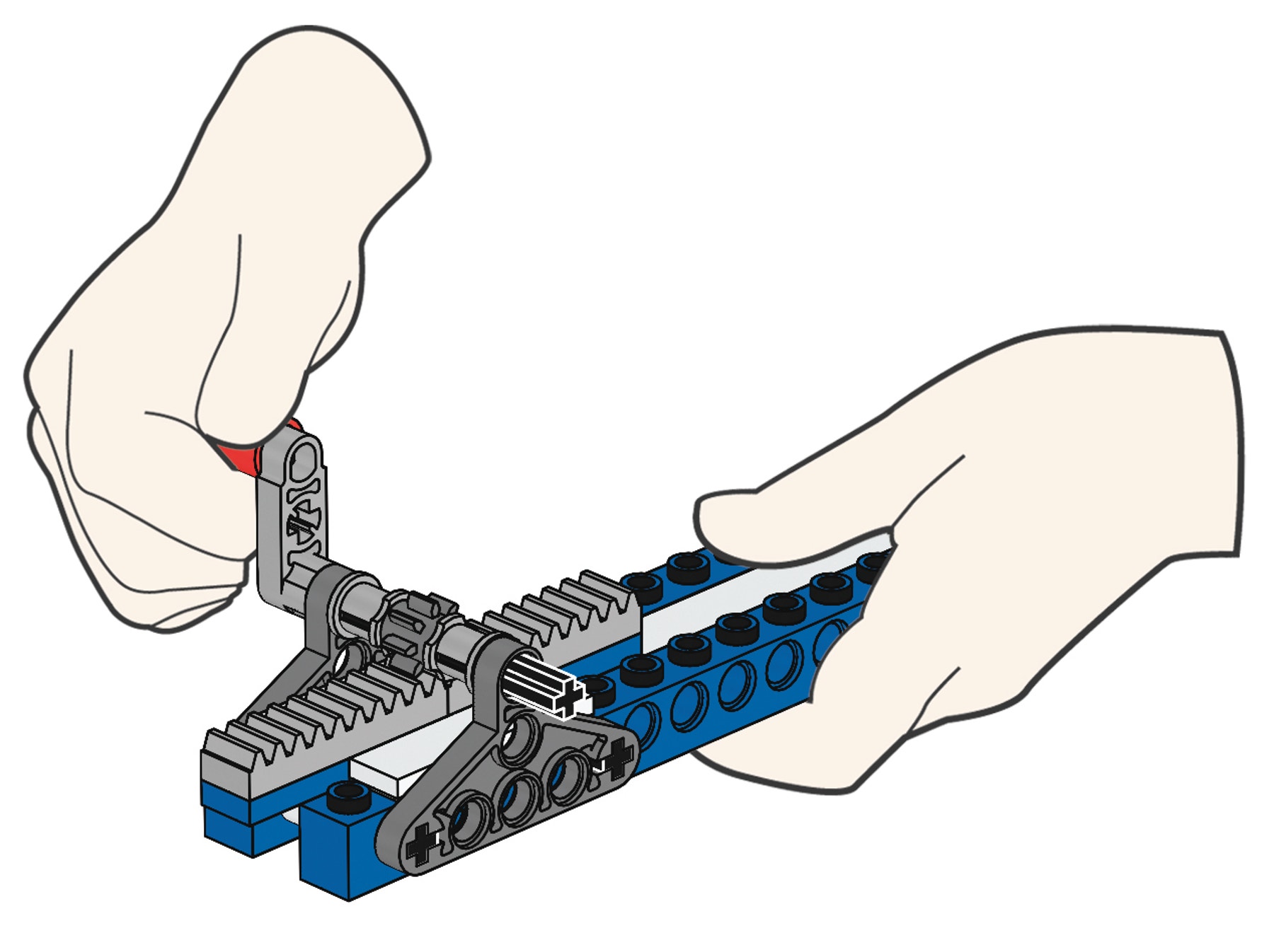
G10
This model shows a rack and pinion gearing. Unlike the previous gears a rack and pinion gearing can only be used for linear motion, not rotary. When the handle is turned the gear rack moves forward or backwards depending on the rotational direction of the small gear (called a pinion).
Continue
(5-10 Minutes)
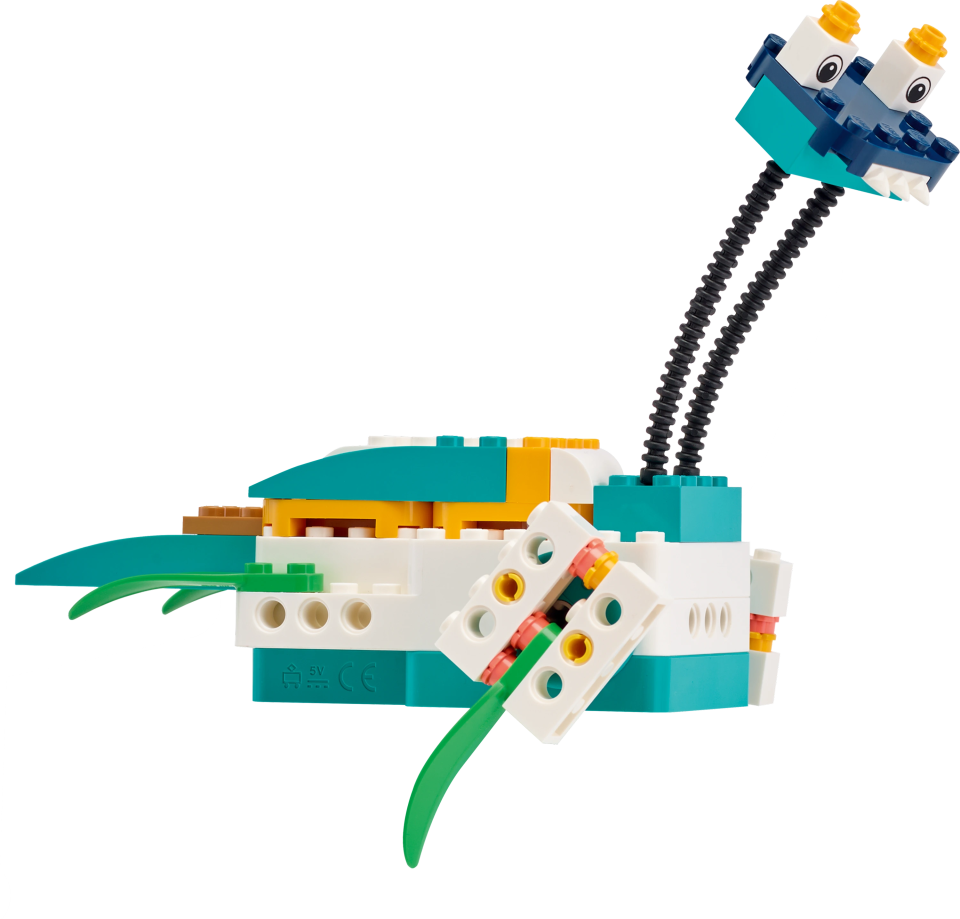
Try other cam lessons!
Now that you have mastered the principles of gears try some of the other lever lessons like Sweeper.
Teacher Support
Students will learn about:
Transferring force and motion efficiently
Gearing, gearing up, down, change of direction
Compound-, periodic-, angle-, differential-, worm-, rack and pinion gearing
9686 Simple & Powered Machines Set (two students per set recommended)
Student Material
Share with:
 Google Classroom